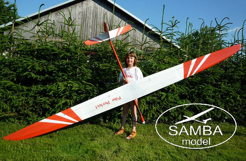
Pike Perfect
Models and spare parts are no longer available
Pike Perfect the arising star in F3J
After many years of tweaking and testing models the time has come for a real scientific approach to F3J. Everybody knows that an athlete is no better than his tools. The new Pike Perfect will fit the task in every way. And this time we have joined up with Philip Kolb to make the model of the future. The model have been worked on for a long time so we are sure we can deliver a "Perfect" product to you as a customer.

Pike Perfect
The Quest for the Ultimate F3J-Model
High quality molded glider designs now dominate the F3J Class. The F3J pilot has to decide which one of the many excellent models currently available he will use in competition. The majority of these models offer excellent performance potential, and are built to the highest standards now expected for competition F3J models.

Author of this article. Philip Kolb with his Pike Superior and Pike Perfect
So what keeps designers and constructors trying hard to push the limits and expending their energy on new designs? Is there still potential performance to be had in the evolution of F3J glider design? Is it worth the time and effort to design a new glider with so many excellent molded models already available?
Considering the gliders flown at the F3J World Championship in 2004 it is interesting that the majority of pilots have embraced the strategy of utilizing two different designs to cope with various weather conditions. Usually a large and light glider is used for floating conditions expected in the morning or evening rounds. However, an agile and stiff model capable of being ballasted is desirable in “launching and landing” conditions, or where there is windy and turbulent weather, a heavier and more agile design offers the best potential for the winning solution.
Pilots choosing one design will find it challenging to adapt to all conditions. One strategy is to choose a design that handles well in normal conditions and then carefully lighten the structure to cope with the dead air rounds. This strategy can prove difficult as the lighter model may not handle as well with the lighter wing loading, and may prove structurally deficient when the competitor attempts to add ballast for normal conditions. Very often these pilots have to admit that there are other models better suited for some conditions and they find themselves at a disadvantage. A pilot who chooses to fly the optimal model for the air present in a particular round may be frustrated by the 3 model rule if he is unlucky enough to damage a given model and find his other optimized models not suitable for the conditions encountered in later rounds.
So it is obvious that the real challenge is to design and construct a new model, which will offer the best performance, over a maximum range of conditions. Some try to continue the evolution of an existing design, step by step, fixing each problem as they are encountered. One popular example is to increase the wingspan and wing area. This method is widely accepted and is helpful, especially when changes need to be made to optimize a heavy model for lighter conditions. Performance improvements can be expected up to a certain point, but in the end, the performance gains will be marginal. These changes can have unexpected results, sometimes adversely affecting the performance of the original design. A change in wingspan for example will have effects on the tail moment arm, tail volume, and lift distribution of the wing. Therefore a complete new design can offer more favorable results, versus redesigning parts on an existing model.

This is the principal I embraced while designing the Pike Perfect
The new model was designed to be the next step, combining both the floating abilities of the large and light F3J gliders, and the maneuverability and launching capabilities of the smaller ones. It is designed with the expectation that no sacrifices have been to the handling qualities of the model. Experience shows that this point is paramount; especially in difficult conditions, when handling qualities prove more important than theoretical performance. These thoughts have led to the design and development of Pike Perfect shown in the following lines and figures.
The geometric design of the wing:
Designing the optimal wing planform, lift distribution, aspect ratio, and the local Reynolds numbers were considered paramount for achieving the desired performance. All of these parameters affect each other, and the designer must make concessions so that the performance goals are achieved. The lift distribution was the first parameter defined because of its fundamental effect on performance.
The circulation is proportional to the local lift at the local chord. As a result the maximum circulation will be at the root chord of the wing, where the lift and chord are maximum. To minimize the induced drag of the wing, the circulation has to decrease elliptically along the span, towards the tip of the wing. Building an elliptical tapered wing offers the advantage of a relatively low tip volume and thereby lighter weighted tips, which helps to keep the plane agile. Conversely, Reynolds numbers will get very low with narrow tips, which increases the airfoil drag, and even worse, will have effects on the stall characteristics of the plane, thereby inducing tip stall problems if the tips are too narrow. The cl_max at the tip is reached earlier than the cl_max at the root. In this case the choice will be a slightly over elliptical planform. The 25% chord line is kept straight in the center of the wing to keep the torsion forces as low as possible and is swept back at the tip. The hinge lines (75% chord) of the flaps and the ailerons are straight to have identical depth of flaps all over the wing.
The next parameter of interest is the aspect ratio. An F3J model will primarily fly at relatively high lift coefficients, as compared to a speed model. The proportion of the induced drag to the entire drag will increase with the lift coefficient, so trying to reduce the induced drag is the way to go. Utilizing an elliptical planform is a good start, but greater performance gains can be expected by increasing the aspect ratio. Increasing the aspect ratio to reduce the induced drag can be achieved by increasing the wingspan or reducing the chord depths of the wing. Considering these facts it became apparent very soon that a small model would have disadvantages compared to a bigger one. Either the induced drag is relatively high because of the low aspect ratio, or a high aspect ratio on a small plane can only be made by building a narrow wing, and accepting the losses in airfoil drag and performance due to low Reynolds numbers.
Faced with these design parameters, it was obvious that it would be necessary to build Pike Perfect as a relatively large glider, with about 75dm² of wing area. The aspect ratio should be about 17 to keep the induced drag low and the Reynolds numbers high. Higher aspect ratios, as flown on several big gliders, have proven to decrease induced drag. If the aspect ratio is too great, the roll rate will decrease and agility will be lost.
The handling of the model must be preserved, so that low altitude “saves” are possible. In conclusion, the wing planform for the all-round F3J model Pike Perfect, can be characterized as follows:
- Large wing area
- Nearly elliptical planform
- Moderate aspect ratio
- Deep chords for high Reynolds numbers

Airfoil:
Modern F3J gliders are equipped with new airfoils developed utilizing computer programs with calculation capabilities. One of the latest inventions in the model airplane scene is the use of an inverse design tool for developing and optimising airfoils. It is able to design the span wise airfoil transitions for the entire wing.
The most popular and readily available tool is the ISES-Code based Xfoil-Program by Dr. Drela. This is a 2D-Solver for calculating airfoil and boundary layer parameters. With the fully inverse design mode .mdes of the Xfoil-Program you have the opportunity to design and modify directly the shape of the velocity distribution and thus the boundary layer parameters and thereby the geometric shape of the airfoil. Most of the popular F3J gliders are equipped with a single airfoil for the whole wing, which is perhaps slightly modified in thickness. For Pike Perfect a non-linear airfoil transition was developed to achieve maximum performance with a minimum of airfoil drag at the most important speeds of flight. For several wing sections the airfoils were optimized for the respective Re*sqrtCl. It is important to pay attention to the zero lift angles, the momentum of the airfoils, and the characteristics of the Cl/a - curve are not varying very much between the sections. I think Dr. Drela and Frits Donker Duijvis were the first to understand the importance of this concept for model airplane design.
The most important demands on the airfoils are:
- to provide a wide maximum of gliding ratio up to 20 m/s speed.
- a high cl_max for carrying weight in windy conditions and for “pulling g´s” in tight thermal turns.
- a reasonable thickness for lightweight, strong, and stiff wing structure.
![]()
Tail and fuselage:
The cruciform tail has become a standard in F3J, although it has more surface drag and usually a little more weight than using a V-tail. These disadvantages quickly disappear when a proper sized cruciform tail yields a powerful rudder, which is handy for tight and accurate circling. Besides, an all-moving elevator will make dealing with the angle of incidence very easy. All in all, the cruciform tail seems to be the best choice of tail configuration because of its easy handling.
Nevertheless, the size, aspect ratio, tail arm, and section of the tail need to be considered as important factors for the stabilization of the plane. The higher the aspect ratio of the rudder and elevator, the steeper the Cl/a-curve will be. With increased aspect ratio, the stabilization factor will increase. Again, to avoid too high airfoil drag on the rudder and elevator, the aspect ratio should not approach extreme values. Using modern airfoils, which will still work fine at Reynolds numbers below 40k, aspect ratios of 7.5 for the elevator and 3 for the rudder are achievable. The HT-airfoils designed by Dr. Drela have shown to be relatively dragless at low Reynolds numbers with no dead-band around the zero-lift angle. Both, elevator and rudder of the Pike Perfect are sectioned with a transition from HT-14 at the root to HT-13 at the tip. To avoid additional drag at the tail, the elevator is assembled very tightly to the rudder, with its leading edge being joined and taped together in front of the rudders leading edge. With this type of assembly, the gap between the elevator parts and the rudder is kept minimal, and no triangular cutouts in the trailing edge of the elevator are necessary to enable the full deflection of the rudder. To provide enough elevator control, especially with fully set crow brake in the landing approach, the elevator area chosen is a little larger than theoretically necessary.
For precise landings, a down swept nose of the fuselage will help to slow down the model, immediately after the touch down. The nose kink of the Pike Perfect is 5° relative to the root chord centerline. The nose is reinforced with additional carbon layers and has only a small canopy, which does not weaken the fuselage structure, so hitting the landing target doesn’t damage the model. The fuselage surface is kept very smooth to avoid additional drag. A very thin tail boom diameter is hard to construct when stiffness and light weight are paramount, so concessions in favor of a light fuselage were made by enlarging the diameter to a reasonable proportion of strength and surface. Finally these dimensions of the fuselage provide a better grip to control the plane under great line tension before the start of working time.
Philip Kolb 2005/2006
English rewriting: Larry Jolly


Pike Perfect ET (Extended tips)
To make something which you call „perfect“ even better seems to be a very hard task. But for the season of 2009 we wanted to offer an add-on to our successful Pike perfect. It didn´t need Extraterrestrial help but some time here on earth to calculate about the pros and cons for an “Extended Tip”-Version of our Pike perfect. Finally with the beginning of the 2009 flying season we are able to offer the Pike perfect ET to our customers.

Here are some lines from the designer Philip Kolb about the new wing tips and their development:
There is a kind of idiom heard very often in soaring: “Bigger is better!”
This simple sentence implicates that larger planes are able to offer more performance. It is true that far, that purely wingspan has the most effects on a sailplanes´ performance. Speaking about the performance of a sailplane means speaking about its lift to drag ratio (L/D) and secondarily about its endurance capabilities (L3/2/D). A higher L/D offers the pilot more ground to cover in the same time as a higher L3/2/D offers longer hang-time. Both are very important in F3J competitions especially in what is called “weak conditions” (low lift, less to no thermal activity).
The typical lift coefficients an F3J-glider flies at are mostly in the range between Cl = 0.6 to Cl = 1.0. In this lift range the proportion of the induced drag to the overall drag of the aircraft is paramount. Induced drag is affected mostly by wingspan (aspect ratio and planform as well), therefore it is obvious that an enlargement in span is the most efficient way to achieve gains in L/D.
While designing the Pike perfect emphasis was not only put on plain performance parameters. An all around F3J model like the Pike perfect should as well offer agility and easy handling so besides performance aeromechanical, structural and practical (economical) parameters were weighted in importance.
Considering this, the most important question coming up was:
“How much of extension is possible without significant structural, aeromechanical and thereby handling drawbacks?”
Since the centre panel planform is preset the freedom of enlarging the tips is not endless due to the given outline of the centre panel. Designing a complete new wing (or better said airplane) might surely be the more optimal consequence, however it is way more economic to extend the tips and not the whole wing as everybody can imagine.
The driving factors for the planform layout were sweep and taper ratio. One has to be very careful not to run into too narrow tips on the one hand side and not too much back sweep on the other.
Excessively narrow tips can lead into unwanted stall characteristics for the tips tend to stall first (higher local lift coefficients!) and higher drag due to lower Reynolds numbers at lower chords. Huge amounts of back sweep have a negative effect on the coupling of torsion and bending loads. This needs to be compensated with a stronger and thereby heavier build up.
The resulting planform of the Pike perfect E.T. in comparison to the original Pike perfect planform is shown in Fig.01.
To contribute the planform with its slightly lower Reynolds numbers on the tip a new tip section was designed. The target was to shift the laminar drag bucket upward so that a higher Clmax is reachable. This action needed to prevent tip stall the more attention was turned on the performance of the airfoil in the range of L/D max and maximum endurance in the given Re-number regime.
The non linear airfoil transition from the tip’s root chord (airfoil PK-91B) to the tip (airfoil PK-995) was designed and developed according to the method described in the Pike perfect development article. For this new transition the airfoils were designed for their local Re*sqrtCl range to offer more equal Clmax values along the span and less drag in the higher lift range from Cl = 0.5 upward.
First calculations show a reduction in sink rate of about 3% with the extended tips compared to the original ones operating at the same wing loading. This reflects in about 20sec. more dead air time out of a 200m launch. Of course flight tests and measurements need to be done to validate these numbers as well as to check out if the drawbacks of the new wingtips which are reflected in less roll rate, less maximal possible bending loads when using the same spar layup and less yaw damping are as minimal as estimated.
March 2009, Philip Kolb

PIKE Perfect E.T. F5J Electro is here.
Ever wanted to fly F3J with electro?
Here is the answer! Same all up weights as the sailplane versions possible and
same performance off course!!!
Empty weights 3550mm 1170g and
3780mm 1230g with "disser" carbon wings! Ready to fly 2000-2200g
Also available now is the Pike Perfection F5J with weights as low as 1600g. See HERE
Development and the production :
The Pike Perfect ET have shown its performance in numerous international F3J competitions and is a fantastic thermal flier. But not all have a winch or towers in hand when they want to fly. So why not convert it to electro? Well up untill now most electro planes of this sort have been to heavy or not the best. But now you can enjoy the happiness of thermalling a true F3J model in any open space - or fly F5J electro competitions with the best tool available. There will be no other model thermalling past you! Enjoy the lunch brake or sunset at your home place now. The Pike Perfect ET have been developed over many years and will cope with any flying condition.
The electro fuse can also be sold separately to fit your already flying Perfect wings.